The Unified Modeling Language (UML) is a standard language for specifying, visualizing, constructing, and documenting the artifacts of software systems, as well as for business modeling and other non-software systems. The UML represents a collection of best engineering practices that have proven successful in the modeling of large and complex systems. The UML is a very important part of developing objects oriented software and the software development process. The UML uses mostly graphical notations to express the design of software projects. Using the UML helps project teams communicate, explore potential designs, and validate the architectural design of the software.
The Unified Modeling Language (UML) is used to specify, visualize, modify, construct and document the artifacts of an object-oriented software-intensive system under development. UML offers a standard way to visualize a system's architectural blueprints, including elements such as:
§ activities
§ actors
§ business processes
§ database schemas
§ (logical) components
§ programming language statements
§ Reusable software components.
UML combines techniques from data modeling (entity relationship diagrams), business modeling (work flows), object modeling, and component modeling. It can be used with all processes, throughout the software development life cycle, and across different implementation technologies.
Use-Case Diagram
A use case is a set of scenarios that describing an interaction between a user and a system. A use case diagram displays the relationship among actors and use cases. The two main components of a use case diagram are use cases and actors.

An actor is represents a user or another system that will interact with the system you are modeling. A use case is an external view of the system that represents some action the user might perform in order to complete a task.
When to Use: Use Cases Diagrams
Use cases are used in almost every project. They are helpful in exposing requirements and planning the project. During the initial stage of a project most use cases should be defined, but as the project continues more might become visible.
Diagram Building
§ Use cases
How to Draw: Use Cases Diagrams
Use cases are a relatively easy UML diagram to draw, but this is a very simplified example. This example is only meant as an introduction to the UML and use cases.
1. Browse catalog and select items.
These steps would generate this simple use case diagram:

Class Diagram
In software engineering, a class diagram in the Unified Modeling Language (UML) is a type of static structure diagram that describes the structure of a system by showing the system's classes, their attributes, operations (or methods), and the relationships among the classes.
Classes are composed of three things: a name, attributes, and operations. Below is an example of a class.

Class diagrams also display relationships such as containment, inheritance, associations and others. Below is an example of an associative relationship:
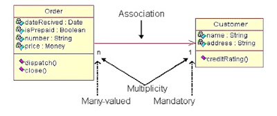
The association relationship is the most common relationship in a class diagram. The association shows the relationship between instances of classes. For example, the class Order is associated with the class Customer. The multiplicity of the association denotes the number of objects that can participate in then relationship. For example, an Order object can be associated to only one customer, but a customer can be associated to many orders.
Another common relationship in class diagrams is a generalization. A generalization is used when two classes are similar, but have some differences. Look at the generalization below:

In this example the classes Corporate Customer and Personal Customer have some similarities such as name and address, but each class has some of its own attributes and operations. The class Customer is a general form of both the Corporate Customer and Personal Customer classes. This allows the designers to just use the Customer class for modules and do not require in-depth representation of each type of customer.
In this example the classes Corporate Customer and Personal Customer have some similarities such as name and address, but each class has some of its own attributes and operations. The class Customer is a general form of both the Corporate Customer and Personal Customer classes. This allows the designers to just use the Customer class for modules and do not require in-depth representation of each type of customer.
When to Use: Class Diagrams
Class diagrams are used in nearly all Object Oriented software designs. Use them to describe the Classes of the system and their relationships to each other.
How to Draw: Class Diagrams
Class diagrams are some of the most difficult UML diagrams to draw. To draw detailed and useful diagrams a person would have to study UML and Object Oriented principles for a long time. Therefore, this page will give a very high level overview of the process. To find list of where to find more information see the Resources page.
Before drawing a class diagram consider the three different perspectives of the system the diagram will present; conceptual, specification, and implementation. Try not to focus on one perspective and try see how they all work together.

Sequence diagram
A sequence diagram in Unified Modeling Language (UML) is a kind of interaction diagram that shows how processes operate with one another and in what order. It is a construct of a Message Sequence Chart. Sequence diagrams are sometimes called event diagrams, event scenarios, and timing diagrams.


A use case is a set of scenarios that describing an interaction between a user and a system. A use case diagram displays the relationship among actors and use cases. The two main components of a use case diagram are use cases and actors.

An actor is represents a user or another system that will interact with the system you are modeling. A use case is an external view of the system that represents some action the user might perform in order to complete a task.
When to Use: Use Cases Diagrams
Use cases are used in almost every project. They are helpful in exposing requirements and planning the project. During the initial stage of a project most use cases should be defined, but as the project continues more might become visible. § Use cases
A use case describes a sequence of actions that provide something of measurable value to an actor and is drawn as a horizontal ellipse.
§ Actors
An actor is a person, organization, or external system that plays a role in one or more interactions with the system.
§ System boundary boxes (optional)
A rectangle is drawn around the use cases, called the system boundary box, to indicate the scope of system. Anything within the box represents functionality that is in scope and anything outside the box is not.
Use cases are a relatively easy UML diagram to draw, but this is a very simplified example. This example is only meant as an introduction to the UML and use cases.
Start by listing a sequence of steps a user might take in order to complete an action. For example a user placing an order with a sales company might follow these steps.
1. Browse catalog and select items.
2. Call sales representative.
3. Supply shipping information.
4. Supply payment information.
5. Receive conformation number from salesperson.
These steps would generate this simple use case diagram:

In software engineering, a class diagram in the Unified Modeling Language (UML) is a type of static structure diagram that describes the structure of a system by showing the system's classes, their attributes, operations (or methods), and the relationships among the classes.
The class diagram is the main building block in object oriented modeling. It is used both for general conceptual modeling of the systematic of the application, and for detailed modeling translating the models into programming code. The classes in a class diagram represent both the main objects and or interactions in the application and the objects to be programmed. In the class diagram these classes are represented with boxes which contain three parts:
Classes are composed of three things: a name, attributes, and operations. Below is an example of a class.

Class diagrams also display relationships such as containment, inheritance, associations and others. Below is an example of an associative relationship:

The association relationship is the most common relationship in a class diagram. The association shows the relationship between instances of classes. For example, the class Order is associated with the class Customer. The multiplicity of the association denotes the number of objects that can participate in then relationship. For example, an Order object can be associated to only one customer, but a customer can be associated to many orders.
Another common relationship in class diagrams is a generalization. A generalization is used when two classes are similar, but have some differences. Look at the generalization below:

In this example the classes Corporate Customer and Personal Customer have some similarities such as name and address, but each class has some of its own attributes and operations. The class Customer is a general form of both the Corporate Customer and Personal Customer classes. This allows the designers to just use the Customer class for modules and do not require in-depth representation of each type of customer.
When to Use: Class Diagrams
Class diagrams are used in nearly all Object Oriented software designs. Use them to describe the Classes of the system and their relationships to each other.How to Draw: Class Diagrams
Class diagrams are some of the most difficult UML diagrams to draw. To draw detailed and useful diagrams a person would have to study UML and Object Oriented principles for a long time. Therefore, this page will give a very high level overview of the process. To find list of where to find more information see the Resources page. Before drawing a class diagram consider the three different perspectives of the system the diagram will present; conceptual, specification, and implementation. Try not to focus on one perspective and try see how they all work together.
When designing classes consider what attributes and operations it will have. Then try to determine how instances of the classes will interact with each other. These are the very first steps of many in developing a class diagram. However, using just these basic techniques one can develop a complete view of the software system.

A sequence diagram in Unified Modeling Language (UML) is a kind of interaction diagram that shows how processes operate with one another and in what order. It is a construct of a Message Sequence Chart. Sequence diagrams are sometimes called event diagrams, event scenarios, and timing diagrams.
A sequence diagram shows, as parallel vertical lines (lifelines), different processes or objects that live simultaneously, and, as horizontal arrows, the messages exchanged between them, in the order in which they occur. This allows the specification of simple runtime scenarios in a graphical manner.


No comments:
Post a Comment